Team 15: Stowable Bait Launcher Blog #5

  1. Give a brief summary of your final device/design and explain what features you’ve designed to address the needs of your problem
    • The final design for the team’s bait launcher is in a “U” shape with a detachable barrel where the compressed air tank is in order to save space and create for easier portability and storage. It’s also designed around schedule 80 PVC in order to create cost saving, while still being able to handle high pressures.
  2. Provide 2-3 key Validation results that indicate how close you have come to meeting your project goals.  Are these results acceptable to you?  How do you think you could do better?
    • The team’s distance validation has been met as it was able to reach the desired 250 yards within the working pressure of 100 psi. Another validation test that the team had done was the ruggedness test where the team tested to see if the tank will fail through cycling of being dropped. The tank passed both test. The tank was able to sustain from 50 cycles at 125 psi without any failures. A drop test was also examined by dropping a 5 lb weight onto the tank to see if if will cause failure at different heights. In addition the storage crate was also tested for ruggedness by dropping from 2-4 feet to make sure it is able to hold the device safely. All validation resulted in desirable outcomes therefore the team would consider it to be very acceptable. Some things in order to make the validation exam better is to cycle the device many more times in order to see if the device will fail over time or usage. The distance validation could also be better if the team had used actual baits on the surf itself in order to verify the distance will still be achieved within surf fishing conditions.
  3. Provide 3-4 representative images to illustrate your device and your results.  Focus on the “final product,” not the process.
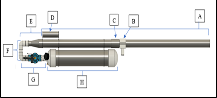
    • Below is are figures that demonstrate the final project of the device and the results the team was able to achieve. Figure 1 is the final device along with the provided crate and bait molds. The second figure is the results from the distance validation found by the team. The third picture displays one of the team members using the device and shows how easy it is to use the device.
Figure 1: Stowable Bait Launcher and Components
Figure 2: Distance Validation
4Figure 3: Testing the functionality of the Device
  • 4. Discuss whether you feel your final device succeeded in providing a solution to your proposed problem.  Are there issues with the device or the problem statement itself?
    • The device has indeed has the functionality and convenience as ones that have already existed in the market, while being cheaper and more portable. Because of so the team would say that the device is providing a solution to the proposed problem. The team did run into some small problems. The team found that the PVC bait mold are not the best method in creating a mold as it becomes difficult to remove it bait and mold. Silicone was a proposed mold material to be used instead. The team has also found that it could have saved more money by using the cheaper schedule 40 PVC instead as it still fits within the working constraints of the device but is more cost effective.
  • 5. Discuss 2-3 major lessons/take-aways you have gained from the year-long capstone course.  How has the experience helped you to grow as an engineer?
    • There were several takeaways the teams had about the capstone project. It helped serve as a reflection which allowed the team to gain a deeper meaning and linking knowledge with experience. Another great takeaway that the team had is the intertwined experience and style of each teammate creating for an interesting team work experience that stressed communication and making sure all teammates are responsible for their part in the project. These things allows the team to grow and gain experience necessary for the work force within the upcoming months.

Team 15: Stowable Bait Launcher Blog #4

1.Over the work period of March 8- March 21, give a description of the work conducted by your team and the progress made on your project.

  • Over the work period of March 8 – March 21 the team has started validation testing on the pressure tank by doing pressure cycling. The team has constructed 90% of the storage crate and has also started the process of acquiring the fishing equipment that will be used for other portions of the validation.

2. For the same work period, discuss any challenges or obstacles (technical or non-technical) that your team has faced. Follow up by explaining the solution implemented or your plan to address the challenge.

  • The team has not encountered any challenges or obstacles within the time period. The team is slightly behind schedule but does not anticipate any major drawbacks that will cause them to not deliver a functioning device on time.

3. Describe the current status of your Team’s Validation Plan implementation. If possible, provide some preliminary results and explain how the results relate to a project goal or design expectation.

  • Currently the team is testing the tank by pressure cycling it. The team has completed 25 cycles without seeing any mechanical failures, the goal is to complete 50 cycles to ensure that the tank will not experience any failures that could potentially yield the device unsafe for use or that may harm the user. The team has also validated the size component of the device and its storage create (with them being about 4 feet in length and 2 feet in width) by testing to sees if it will fit into different vehicle types.

4. Give at least 3 figures that are representative of the current status of your project.  Explain these figures and their importance to your work.

  • The figures below depict the current status of the project. Figures 1 & 2 show the storage crate that was constructed to hold the device and the pump. Figures 3 & 4 show the tank being filled with a compressor to conduct the pressure cycling section of the team’s validation plan.
Figure 1. Side View – Storage Crate
Figure 2. Top View – Launcher Storage Crate
Figure 3. Top View – Pressure Tank Being Filled
Figure 4. Front View – Pressure Tank, Cycling Testing

Team 15: Stowable Bait Launcher Blog #3

1.Over the work period of February 9- March 7, give a description of the work conducted by your team and the progress made on your project.

  • Over the work period of February 9 – March 7, the team has worked on completing the prototype for the bait launcher. The team worked on modifying the sprinkler valve to create the release mechanism, as well as fit a PVC cap with the pressure gauge and a Schrader valve. Team 15 has attached the release mechanism and the cap (previously mentioned) to the pressure tank and has tested it by filling it to a pressure of 135 psi.

2. For the same work period, discuss any challenges or obstacles (technical or non-technical) that your team has faced. Follow up by explaining the solution implemented or your plan to address the challenge.

  • One of the challenges faced by the team was when trying out the launcher for the first time. To check on its initial functionality the team tested the device by filling the tank and noticed that there was a small leak somewhere in the valve. It was determined that the leak might be originating from one of the screw holes; to fix the issue, the team took out the screw, epoxied the hole and placed the screw back in before it dried to seal it off.

3. Describe your team’s plan for the work period from March 8th to the submission of your design review presentations.  Explain any anticipated challenges.

  • For the work period from March 8th to the submission of the design review presentation the team plans on finishing all validation testing on the device, perform final modifications based on the results of the tests, author an assembly and instructions manual, and finally present the working prototype with information about its final performance. The team does not anticipate any challenges for the remaining time period.

4. Give 2-3 figures that are representative of the current status of your project.  Explain these figures and their importance to your work.

  • The figures below show the pressure tanks and the two important components that were attached to it. Figure 1 shows the assembled pressure tank, Figure 2 shows side and top views of the cap that was fitted with the pressure gauge and the Schrader valve, as well as the inside of the cap to further show how it was assembled. Finally, Figure 3 shows the completed modified sprinkler valve.
Figure 1. Assembled Pressure Tank with Release Mechanism, Barrel Supports and Pressure Gauge
Figure 2. PVC Cap Fitted with Pressure Gauge and Schrader Valve (Multiple Views)
Figure 3. Release Mechanism – Modified Sprinkler Valve

Team 15: Stowable Bait Launcher Blog #2

1.Over the work period of January 26 – February 8, give a description of the work conducted by your team and the progress made on your project.

  • Over the work period between January 26 – February 8 the team has begun construction of the prototype for the stowable bait launcher. Dry fitment of all the parts was necessary to adjust the dimensions of the CAD drawings for the barrel supports and bipod attachment. During this work period the team has also sent the CAD drawings for the barrel supports to the UH 3D printing lab; they were ready on February 7th, picked up and will be incorporated to the device.

2. For the same work period, discuss any challenges or obstacles (technical or non-technical) that your team has faced. Follow up by explaining the solution implemented or your plan to address the challenge.

  • The team only had two challenges in since the last entry. The first obstacle was with the 3D printed parts. More specifically the tank to barrel supports were not solid enough with the 30% infill. To solve this the team asked to have the two supports reprinted at 100% infill. The parts finished earlier today 2/8/19 and are waiting to be picked up. The second challenged faced was the team forgetting to order a coupling that connected a junction of the air tank. To prevent this issue from delaying the completion of the prototype, the team decided to hold the parts together with duct tape, continue with the fabrication of the prototype and order the missing part. After the part arrived it was easy for the team to incorporate the coupling on the device.

3. Describe your team’s plan for the work period from February 9th to the submission of your progress report presentations.  Explain any anticipated challenges.

  • For the following work period the team plans on starting the fabrication of the storage box for the device. The team will also obtain the fishing equipment that will be utilized and fabricate the molds for the bait. The team is not expecting any challenges or deviations in the original schedule to complete the prototype and begin validation testing on February 16th.

4. Give 2-3 figures that are representative of the current status of your project.  Explain these figures and their importance to your work.

  • Team 15 has started the fabrication of the stowable bait launcher prototype.
Assembled Prototype of the Stowable Bait Launcher
3D printed parts
For the time being, the bipod attachment is being held together with two stainless bolts

Team 15: Stowable Bait Launcher Blog #1

1.Provide an update of any changes to your project scope, plan, or tasks made during the winter break. If there are no significant changes to address, please state such and provide a review of your project plan for the spring.

  • There are no changes to Team 15’s project scope or plan. For Spring 2019 the team is planning on fabricating the prototype for a Stowable Bait Launching device, and conduct validation testing on the device. The prototype is expected to be completed by February 15th. All testing will be conducted by April 19th. There are currently no foreseeable drawbacks and progress is on schedule.

2. Describe any progress made on your project since the semester has begun – this can include purchase orders, resource organization, fabrication, or FINALIZATION of design schematics.

  • Since the start of the semester, Team 15 has purchased the materials needed to start the fabrication of the device. The parts that were ordered online arrived on January 22nd.

3. Provide 2-3 representative graphics that give a good idea of the current status of the project. Theses could be schematics, tables/figures, or photos. Explain how they related to the current status of the project.

  • Currently Team 15 has ordered the parts to fabricate a prototype of the device according to the designs below.
Finalized Design of Bait Launcher with Parts
Description and Dimensions of Launcher Segments
Design of Fully Assembled Device

4. Give a preview of the work planned for the next 2 weeks.

  • For the next two weeks Team 15 will complete instructions for the fabrication of the device and begin construction of the bait launcher.